Last Updated on January 14, 2021 by Admin
Appendix Lab – Observing ARP with the Windows CLI, IOS CLI, and Wireshark Answers
Lab – Observing ARP with the Windows CLI, IOS CLI, and Wireshark (Answers Version)
Answers Note: Red font color or Gray highlights indicate text that appears in the instructor copy only.
Topology

Addressing Table
|
Device |
Interface |
IP Address |
Subnet Mask |
Default Gateway |
|
R1 |
G0/1 |
192.168.1.1 |
255.255.255.0 |
N/A |
|
S1 |
VLAN 1 |
192.168.1.11 |
255.255.255.0 |
192.168.1.1 |
|
S2 |
VLAN 1 |
192.168.1.12 |
255.255.255.0 |
192.168.1.1 |
|
PC-A |
NIC |
192.168.1.3 |
255.255.255.0 |
192.168.1.1 |
|
PC-B |
NIC |
192.168.1.2 |
255.255.255.0 |
192.168.1.1 |
Objectives
Part 1: Build and Configure the Network
Part 2: Use the Windows ARP Command
Part 3: Use the IOS Show ARP Command
Part 4: Use Wireshark to Examine ARP Exchanges
Background / Scenario
The Address Resolution Protocol (ARP) is used by TCP/IP to map a Layer 3 IP address to a Layer 2 MAC address. When a frame is placed on the network, it must have a destination MAC address. To dynamically discover the MAC address for the destination device, an ARP request is broadcast on the LAN. The device that contains the destination IP address responds, and the MAC address is recorded in the ARP cache. Every device on the LAN keeps its own ARP cache, or small area in RAM that holds ARP results. An ARP cache timer removes ARP entries that have not been used for a certain period of time.
ARP is an excellent example of performance tradeoff. With no cache, ARP must continually request address translations each time a frame is placed on the network. This adds latency to the communication and could congest the LAN. Conversely, unlimited hold times could cause errors with devices that leave the network or change the Layer 3 address.
A network administrator should be aware of ARP, but may not interact with the protocol on a regular basis. ARP is a protocol that enables network devices to communicate with the TCP/IP protocol. Without ARP, there is no efficient method to build the datagram Layer 2 destination address. Also, ARP is a potential security risk. ARP spoofing, or ARP poisoning, is a technique used by an attacker to inject the wrong MAC address association in a network. An attacker forges the MAC address of a device, and frames are sent to the wrong destination. Manually configuring static ARP associations is one way to prevent ARP spoofing. Finally, an authorized MAC address list may be configured on Cisco devices to restrict network access to only approved devices.
In this lab, you will use the ARP commands in Cisco routers and in Windows to display the ARP table. You will also clear the ARP cache and add static ARP entries.
Note: The routers used with CCNA hands-on labs are Cisco 1941 Integrated Services Routers (ISRs) with Cisco IOS Release 15.2(4)M3 (universalk9 image). The switches used are Cisco Catalyst 2960s with Cisco IOS Release 15.0(2) (lanbasek9 image). Other routers, switches, and Cisco IOS versions can be used. Depending on the model and Cisco IOS version, the commands available and the output produced might vary from what is shown in the labs. Refer to the Router Interface Summary Table at the end of this lab for the correct interface identifiers.
Note: Make sure that the routers and switches have been erased and have no startup configurations. If you are unsure, contact your instructor.
Answers Note: Refer to the Answers Lab Manual for the procedures to initialize and reload devices.
Answers Note: Some of the ARP commands in Windows Vista or later operating systems will require administrator privileges.
Required Resources
- 1 Router (Cisco 1941 with Cisco IOS Release 15.2(4)M3 universal image or comparable)
- 2 Switches (Cisco 2960 with Cisco IOS Release 15.0(2) lanbasek9 image or comparable)
- 2 PCs (Windows 7, 8, or 10 with terminal emulation program, such as Tera Term and Wireshark installed)
- Console cables to configure the Cisco IOS devices via the console ports
- Ethernet cables as shown in the topology
Note: The Fast Ethernet interfaces on Cisco 2960 switches are autosensing and an Ethernet straight-through cable may be used between switches S1 and S2. If using another Cisco switch model, it may be necessary to use an Ethernet crossover cable.
Part 1: Build and Configure the Network
Step 1: Cable the network according to the topology.
Step 2: Configure the IP addresses for the devices according to the Addressing Table.
Step 3: Verify network connectivity by pinging all the devices from PC-B.
Part 2: Use the Windows ARP Command
The arp command allows the user to view and modify the ARP cache in Windows. You access this command from the Windows command prompt.
Step 1: Display the ARP cache.
- Open a command window on PC-A and type arp.
C:\> arp
Displays and modifies the IP-to-Physical address translation tables used by
address resolution protocol (ARP).
ARP -s inet_addr eth_addr [if_addr]
ARP -d inet_addr [if_addr]
ARP -a [inet_addr] [-N if_addr] [-v]
-a Displays current ARP entries by interrogating the current
protocol data. If inet_addr is specified, the IP and Physical
addresses for only the specified computer are displayed. If
more than one network interface uses ARP, entries for each ARP
table are displayed.
-g Same as -a.
-v Displays current ARP entries in verbose mode. All invalid
entries and entries on the loop-back interface will be shown.
inet_addr Specifies an internet address.
-N if_addr Displays the ARP entries for the network interface specified
by if_addr.
-d Deletes the host specified by inet_addr. inet_addr may be
wildcarded with * to delete all hosts.
-s Adds the host and associates the Internet address inet_addr
with the Physical address eth_addr. The Physical address is
given as 6 hexadecimal bytes separated by hyphens. The entry
is permanent.
eth_addr Specifies a physical address.
if_addr If present, this specifies the Internet address of the
interface whose address translation table should be modified.
If not present, the first applicable interface will be used.
Example:
> arp -s 157.55.85.212 00-aa-00-62-c6-09 …. Adds a static entry.
> arp -a …. Displays the arp table.
- Examine the output.
What command would be used to display all entries in the ARP cache?
____________________________________________________________________________________
arp –a
What command would be used to delete all ARP cache entries (flush ARP cache)?
____________________________________________________________________________________
arp –d *
What command would be used to delete the ARP cache entry for 192.168.1.11?
____________________________________________________________________________________
arp –d 192.168.1.11
- Type arp –a to display the ARP table.
C:\> arp –a
Interface: 192.168.1.3 — 0x13
Internet Address Physical Address Type
192.168.1.1 50-3d-e5-aa-c0-a1 dynamic
224.0.0.22 01-00-5e-00-00-16 static
C:\> arp -a
No ARP Entries Found.
- Ping from PC-A to PC-B to dynamically add entries in the ARP cache.
C:\> ping 192.168.1.2
Interface: 192.168.1.3 — 0x13
Internet Address Physical Address Type
192.168.1.1 50-3d-e5-aa-c0-a1 dynamic
192.168.1.2 00-21-70-cf-3d-cc dynamic
224.0.0.22 01-00-5e-00-00-16 static
What is the physical address for the host with IP address of 192.168.1.2?
____________________________________________________________________________________
00-21-70-cf-3d-cc
Step 2: Adjust entries in the ARP cache manually.
To delete entries in ARP cache, issue the command arp –d {inet-addr | *}. Addresses can be deleted individually by specifying the IP address, or all entries can be deleted with the wildcard *.
Verify that the ARP cache contains the following entries: the R1 G0/1 default gateway (192.168.1.1), PC-B (192.168.1.2) and both switches (192.168.1.11 and 192.168.1.12).
- From PC-A, ping all the addresses in the Address Table.
- Verify that all the addresses have been added to the ARP cache. If the address is not in ARP cache, ping the destination address and verify that the address was added to the ARP cache.
C:\> arp –a
Interface: 192.168.1.3 — 0x13
Internet Address Physical Address Type
192.168.1.1 50-3d-e5-aa-c0-a1 dynamic
192.168.1.2 00-21-70-cf-3d-cc dynamic
192.168.1.11 00-09-b7-e6-c0-40 dynamic
192.168.1.12 00-17-e0-2c-56-c0 dynamic
192.168.1.255 ff-ff-ff-ff-ff-ff static
224.0.0.22 01-00-5e-00-00-16 static
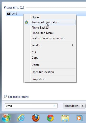
- As an administrator, access the command prompt. Click the Start icon, and in the Search programs and file box, type cmd. When the cmd icon appears, right-click the icon and select Run as administrator. Click Yes to allow this program to make changes.
- In the Administrator command prompt window, type arp –d *. This command deletes all the ARP cache entries. Verify that all the ARP cache entries are deleted by typing arp –a at the command prompt.
C:\windows\system32> arp –d *
C:\windows\system32> arp –a
No ARP Entries Found.
- Wait a few minutes. The Neighbor Discovery protocol starts to populate the ARP cache again.
C:\> arp –a
Interface: 192.168.1.3 — 0xb
Internet Address Physical Address Type
192.168.1.255 ff-ff-ff-ff-ff-ff static
- From PC-A, ping PC-B (192.168.1.2) and the switches (192.168.1.11 and 192.168.1.12) to add the ARP entries. Verify that the ARP entries have been added to the cache.
C:\> arp –a
Interface: 192.168.1.3 — 0xb
192.168.1.1 50-3d-e5-aa-c0-a1 dynamic
192.168.1.2 00-21-70-cf-3d-cc dynamic
192.168.1.11 00-09-b7-e6-c0-40 dynamic
192.168.1.12 00-17-e0-2c-56-c0 dynamic
192.168.1.255 ff-ff-ff-ff-ff-ff static
224.0.0.22 01-00-5e-00-00-16 static
- Record the physical address for switch S2.
___________________________________ Answers will vary. 0c-17-e0-2c-56-c0 in this case. - Delete a specific ARP cache entry by typing arp –d inet-addr. At the command prompt, type arp -d 192.168.1.12 to delete the ARP entry for S2.
C:\windows\system32> arp –d 192.168.1.12 - Type arp –a to verify that the ARP entry for S2 has been removed from the ARP cache.
C:\> arp –a
Interface: 192.168.1.3 — 0x13
Internet Address Physical Address Type
192.168.1.1 50-3d-e5-aa-c0-a1 dynamic
192.168.1.2 00-21-70-cf-3d-cc dynamic
192.168.1.11 00-09-b7-e6-c0-40 dynamic
224.0.0.22 01-00-5e-00-00-16 static
Part 3: Use the IOS show arp Command
The Cisco IOS can also display the ARP cache on routers and switches with the show arp or show ip arp command.
Step 1: Display ARP entries on router R1.
R1# show arp
Protocol Address Age (min) Hardware Addr Type Interface
Internet 192.168.1.1 – 503d.e5aa.c0a1 ARPA GigabitEthernet0/1
Internet 192.168.1.2 29 0021.70cf.3dcc ARPA GigabitEthernet0/1
Internet 192.168.1.3 10 0026.b9dd.0091 ARPA GigabitEthernet0/1
Internet 192.168.1.12 37 0017.e02c.56c0 ARPA GigabitEthernet0/1
R1#
Notice there is no Age (-) for the first entry, router interface G0/1 (the LAN default gateway). The Age is the number of minutes (min) that the entry has been in ARP cache and is incremented for the other entries. The Neighbor Discovery protocol populates the PC-A and PC-B IP and MAC address ARP entries.
Step 2: Add ARP entries on router R1.
You can add ARP entries to the ARP table of the router by pinging other devices.
- Ping switch S1.
R1# ping 192.168.1.11
Type escape sequence to abort.
Sending 5, 100-byte ICMP Echos to 192.168.1.11, timeout is 2 seconds:
..!!!
Success rate is 60 percent (3/5), round-trip min/avg/max = 1/1/1 ms
- Verify that an ARP entry for switch S1 has been added to the ARP table of R1.
R1# show ip arp
Protocol Address Age (min) Hardware Addr Type Interface
Internet 192.168.1.1 – 503d.e5aa.c0a1 ARPA GigabitEthernet0/1
Internet 192.168.1.2 32 0021.70cf.3dcc ARPA GigabitEthernet0/1
Internet 192.168.1.3 13 0026.b9dd.0091 ARPA GigabitEthernet0/1
Internet 192.168.1.11 0 0009.b7e6.c040 ARPA GigabitEthernet0/1
Internet 192.168.1.12 40 0017.e02c.56c0 ARPA GigabitEthernet0/1
Step 3: Display ARP entries on switch S1.
S1# show ip arp
Protocol Address Age (min) Hardware Addr Type Interface
Internet 192.168.1.11 – 0009.b7e6.c040 ARPA VLAN1
Internet 192.168.1.12 42 0017.e02c.56c0 ARPA VLAN1
Internet 192.168.1.1 3 503d.e5aa.c0a1 ARPA VLAN1
Internet 192.168.1.3 16 0026.b9dd.0091 ARPA VLAN1
Step 4: Add ARP entries on switch S1.
By pinging other devices, ARP entries can also be added to the ARP table of the switch.
- From switch S1, ping PC-B.
S1# ping 192.168.1.2
Type escape sequence to abort.
Sending 5, 100-byte ICMP Echos to 192.168.1.2, min/avg/max = 1/201/1002 ms
.!!!!
Success rate is 80 percent (4/5), round-trip min/avg/max = 1/2/8 ms
- Verify that the ARP entry for PC-B has been added to ARP table of S1.
S1# show ip arp
Protocol Address Age (min) Hardware Addr Type Interface
Internet 192.168.1.11 – 0009.b7e6.c040 ARPA VLAN1
Internet 192.168.1.12 44 0017.e02c.56c0 ARPA VLAN1
Internet 192.168.1.1 5 503d.e5aa.c0a1 ARPA VLAN1
Internet 192.168.1.3 17 0026.b9dd.0091 ARPA VLAN1
Internet 192.168.1.2 0 0021.70cf.3dcc ARPA VLAN1
Part 4: Use Wireshark to Examine ARP Exchanges
In Part 4, you will examine ARP exchanges by using Wireshark to capture and evaluate the ARP exchange. You will also examine network latency caused by ARP exchanges between devices.
Step 1: Configure Wireshark for packet captures.
- Start Wireshark.
- Choose the network interface to use for capturing the ARP exchanges.
Step 2: Capture and evaluate ARP communications.
- Start capturing packets in Wireshark. Use the filter to display only ARP packets.
- Flush the ARP cache by typing the arp –d * command at the command prompt.
- Verify that the ARP cache has been cleared.
- Send a ping to the default gateway, using the ping 192.168.1.1 command.
- Stop the Wireshark capture after pinging to the default gateway is finished.
- Examine the Wireshark captures for the ARP exchanges in the packet details pane.
What was the first ARP packet? ___________________________ ARP request

Fill in the following table with information about your first captured ARP packet.
|
Field |
Value |
|
Sender MAC address |
00:26:b9:dd:00:91 – Answers will vary. |
|
Sender IP address |
192.168.1.3 |
|
Target MAC address |
00:00:00:00:00:00 |
|
Target IP address |
192.168.1.1 |
What was the second ARP packet? ______________________________ ARP reply

Fill in the following table with information about your second captured ARP packet.
|
Field |
Value |
|
Sender MAC address |
50:3d:e5:aa:c0:a1 – Answers will vary. |
|
Sender IP address |
192.168.1.1 |
|
Target MAC address |
00:26:b9:dd:00:91 – Answers will vary. |
|
Target IP address |
192.168.1.3 |
Step 3: Examine network latency caused by ARP.
- Clear the ARP entries on PC-A.
- Clear the ARP entries on S2.
S2# clear arp-cache - Start a Wireshark capture.
- Ping switch S2 (192.168.1.12). The ping should be successful after the first echo request.
Note: If all the pings were successful, S1 should be reloaded to observe network latency with ARP.
C:\> ping 192.168.1.12
Pinging 192.168.1.12 with 32 bytes of data:
Request timed out.
Reply from 192.168.1.12: bytes=32 time<1ms TTL=255
Reply from 192.168.1.12: bytes=32 time<1ms TTL=255
Reply from 192.168.1.12: bytes=32 time=1ms TTL=255
Ping statistics for 192.168.1.12:
Packets: Sent = 4, Received = 3, Lost = 1 (25% loss),
Approximate round trip times in milli-seconds:
Minimum = 0ms, Maximum = 1ms, Average = 0ms
- Stop the Wireshark capture after the pinging is finished. Use the Wireshark filter to display only ARP and ICMP outputs. In Wireshark, type arp or icmp in the Filter: entry area.
-
After the ARP entry for S2 was added to the ARP cache, the last three ICMP exchanges were successful, as displayed in frames 11-12, 14-15, and 16-17.
As displayed in the Wireshark capture, ARP is an excellent example of performance tradeoff. With no cache, ARP must continually request address translations each time a frame is placed on the network. This adds latency to the communication and could congest the LAN.
Examine the Wireshark capture. In this example, frame 5 is the first ICMP request sent by PC-A to S2. Because there is no ARP entry for S2, an ARP request was sent to the management IP address of S2 asking for the MAC address. During the ARP exchanges, the echo request did not receive a reply before the request was timed out. (frames 3 – 7)

Reflection
- How and when are static ARP entries removed?______________________________________________________________________________________________________________________________________________________________________________
They are deleted manually. - Why do you want to add static ARP entries in the cache?______________________________________________________________________________________________________________________________________________________________________________
A static ARP entry can mitigate ARP spoofing or poisoning in the network. - If ARP requests can cause network latency, why is it a bad idea to have unlimited hold times for ARP entries?______________________________________________________________________________________________________________________________________________________________________________
Unlimited hold times could cause errors with devices that leave the network or change the Layer 3 address.
Router Interface Summary Table
|
Router Interface Summary |
||||
|
Router Model |
Ethernet Interface #1 |
Ethernet Interface #2 |
Serial Interface #1 |
Serial Interface #2 |
|
1800 |
Fast Ethernet 0/0 (F0/0) |
Fast Ethernet 0/1 (F0/1) |
Serial 0/0/0 (S0/0/0) |
Serial 0/0/1 (S0/0/1) |
|
1900 |
Gigabit Ethernet 0/0 (G0/0) |
Gigabit Ethernet 0/1 (G0/1) |
Serial 0/0/0 (S0/0/0) |
Serial 0/0/1 (S0/0/1) |
|
2801 |
Fast Ethernet 0/0 (F0/0) |
Fast Ethernet 0/1 (F0/1) |
Serial 0/1/0 (S0/1/0) |
Serial 0/1/1 (S0/1/1) |
|
2811 |
Fast Ethernet 0/0 (F0/0) |
Fast Ethernet 0/1 (F0/1) |
Serial 0/0/0 (S0/0/0) |
Serial 0/0/1 (S0/0/1) |
|
2900 |
Gigabit Ethernet 0/0 (G0/0) |
Gigabit Ethernet 0/1 (G0/1) |
Serial 0/0/0 (S0/0/0) |
Serial 0/0/1 (S0/0/1) |
|
Note: To find out how the router is configured, look at the interfaces to identify the type of router and how many interfaces the router has. There is no way to effectively list all the combinations of configurations for each router class. This table includes identifiers for the possible combinations of Ethernet and Serial interfaces in the device. The table does not include any other type of interface, even though a specific router may contain one. An example of this might be an ISDN BRI interface. The string in parenthesis is the legal abbreviation that can be used in Cisco IOS commands to represent the interface. |
||||
Device Configs
Router R1
R1#show run
Building configuration…
Current configuration : 1165 bytes
!
version 15.2
service timestamps debug datetime msec
service timestamps log datetime msec
no service password-encryption
!
hostname R1
!
boot-start-marker
boot-end-marker
!
!
!
no aaa new-model
memory-size iomem 15
!
!
ip cef
no ipv6 cef
multilink bundle-name authenticated
!
!
interface Embedded-Service-Engine0/0
no ip address
shutdown
!
interface GigabitEthernet0/0
no ip address
shutdown
duplex auto
speed auto
!
interface GigabitEthernet0/1
ip address 192.168.1.1 255.255.255.0
duplex auto
speed auto
!
interface Serial0/0/0
no ip address
shutdown
clock rate 2000000
!
interface Serial0/0/1
no ip address
shutdown
!
ip forward-protocol nd
!
no ip http server
no ip http secure-server
!
!
control-plane
!
!
line con 0
line aux 0
line 2
no activation-character
no exec
transport preferred none
transport input all
transport output pad telnet rlogin lapb-ta mop udptn v120 ssh
stopbits 1
line vty 0 4
login
transport input all
!
scheduler allocate 20000 1000
!
end
Switch S1
S1#show run
Building configuration…
Current configuration : 1305 bytes
!
version 15.0
no service pad
service timestamps debug datetime msec
service timestamps log datetime msec
no service password-encryption
!
hostname S1
!
boot-start-marker
boot-end-marker
!
no aaa new-model
system mtu routing 1500
!
!spanning-tree mode pvst
spanning-tree extend system-id
!
vlan internal allocation policy ascending
!
!
interface FastEthernet0/1
!
interface FastEthernet0/2
!
interface FastEthernet0/3
!
interface FastEthernet0/4
!
interface FastEthernet0/5
!
interface FastEthernet0/6
!
interface FastEthernet0/7
!
interface FastEthernet0/8
!
interface FastEthernet0/9
!
interface FastEthernet0/10
!
interface FastEthernet0/11
!
interface FastEthernet0/12
!
interface FastEthernet0/13
!
interface FastEthernet0/14
!
interface FastEthernet0/15
!
interface FastEthernet0/16
!
interface FastEthernet0/17
!
interface FastEthernet0/18
!
interface FastEthernet0/19
!
interface FastEthernet0/20
!
interface FastEthernet0/21
!
interface FastEthernet0/22
!
interface FastEthernet0/23
!
interface FastEthernet0/24
!
interface GigabitEthernet0/1
!
interface GigabitEthernet0/2
!
interface Vlan1
ip address 192.168.1.11 255.255.255.0
!
ip http server
ip http secure-server
!
line con 0
line vty 5 15
!
end
Switch S2
S2#show run
Building configuration…
Current configuration : 1313 bytes
!
version 15.0
no service pad
service timestamps debug datetime msec
service timestamps log datetime msec
no service password-encryption
!
hostname S2
!
boot-start-marker
boot-end-marker
!
no aaa new-model
system mtu routing 1500
!
!
spanning-tree mode pvst
spanning-tree extend system-id
!
vlan internal allocation policy ascending
!
!
interface FastEthernet0/1
!
interface FastEthernet0/2
!
interface FastEthernet0/3
!
interface FastEthernet0/4
!
interface FastEthernet0/5
!
interface FastEthernet0/6
!
interface FastEthernet0/7
!
interface FastEthernet0/8
!
interface FastEthernet0/9
!
interface FastEthernet0/10
!
interface FastEthernet0/11
!
interface FastEthernet0/12
!
interface FastEthernet0/13
!
interface FastEthernet0/14
!
interface FastEthernet0/15
!
interface FastEthernet0/16
!
interface FastEthernet0/17
!
interface FastEthernet0/18
!
interface FastEthernet0/19
!
interface FastEthernet0/20
!
interface FastEthernet0/21
!
interface FastEthernet0/22
!
interface FastEthernet0/23
!
interface FastEthernet0/24
!
interface GigabitEthernet0/1
!
interface GigabitEthernet0/2
!
interface Vlan1
ip address 192.168.1.12 255.255.255.0
!
ip http server
ip http secure-server
!
line con 0
line vty 5 15
!
end